Section Cut Arrows
Sectional Views Basic Blueprint Reading
Drawing Section Lines Autocad 2d Drafting Object Properties Interface Autocad Forums

Sectional Views Section Views Ppt Video Online Download
Eng 004 Lecture 17

S Ection V Iews What Is A Section View See Inside An Object Why Section View Complex Interior Geometry Clarify The Interior Construction Can T Clearly Ppt Download

To Create A Cross Section View Autocad 2020 Autodesk Knowledge Network
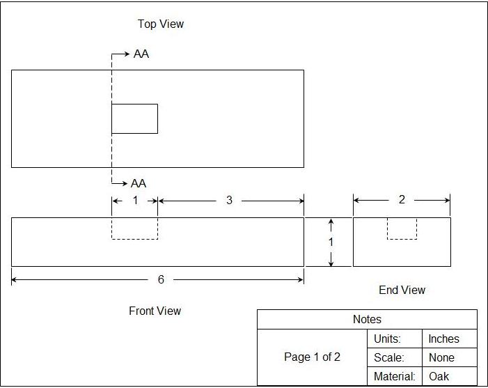
The direction of the plane through which the section is cut is often represented on plan drawings and elevations by a line of long and short dashes called a section plane.
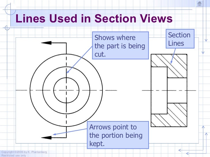
Section cut arrows. The arrows in show the direction of view. You have to build the offset x section in the model ie sketch the cutting plane. Arrows for cross section cutting line how does one add the arrowheads to a cross section cutting line.
The arrows at the ends of cutting plane line point in the direction of sight for front section. The result is called a front section or front view in section since it replaces the front view in the drawing. 7 4 interpreting cutting planes and sections.
Back to topic listing. Hp z420 workstation intel xeon cpu e5 1603 0 2 80 ghz 2 80 ghz 12 0 gb ram windows 7 professional 64 bit 3d connexion space pilot solid edge st9 mp1 inventor professional 2015 autocad 2015 solidworks 2015 report. You should change the keyboard input to unicode hex input for this method to work.
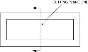
A cutting plane is represented on a drawing by a cutting plane line. Cutting plane is a frontal plane and appears as a line in the top view. Similar to alt code you can use option codes in mac to insert arrow symbols.
Option code for mac. Message 2 of 3 yoder s. Since the view was in line with the part the section arrows disappeared on their own.
I have looked under cross section sectional views arrowheads and leaders. This holds for first and third angle projection quick navigation general top. Press one of the option keys and then type the hexadecimal code as in the above table.
To Display A 2d Cross Section View

Course 200c F14 Steinfeld Session 938596 Studiomaven

Basic Blueprint Reading

Drawing Section Lines No Hashed Lines Present Autodesk Community Fusion 360
Engineering Drawings

Making A Block For A Door Cad Cam Engineering Worldwide
Https Learning Hccs Edu Faculty Allie Jones Dftg1305 Summer 2018 Lecuture Notes Chapter 8 Section Views
Https Learning Hccs Edu Faculty Edward Osakue Dftg 1333 Mechanical Drafting Course Notes Unit 7 Section View Drawings At Download File
Chapter 3 Sectioning

To Create A Full Section View Autocad 2019 Autodesk Knowledge Network

Drawing Basics

Ch 8 Section Views Objective Learn How To Create Section Views And Ppt Video Online Download
Cad Block Of Section Arrow Cadblocksfree Cad Blocks Free